The elderly RS-232 and RS-422 standards define the physical and electrical characteristics of many serial interfaces. Unlike modern serial buses, they only accommodate a simple connection between two devices. As with any asynchronous interface, data is sent in short bursts, usually one byte in length. This avoids the need for a precise timing reference at the receiver, a simple crystal oscillator being perfectly adequate. Each byte consists of 8 bits, the least significant byte being sent first. Whenever 7-bit data is transmitted the last bit is available as a parity bit for simple error detection.
Data is transferred between each port and the processor itself via a chip that’s commonly known as a Universal Asynchronous Receiver and Transmitter (UART) or an Asynchronous Communications Interface Adaptor (ACIA). The basic form of this kind of interface is shown below:-
Depending on the type of interface, the TXD and RXD circuits may consist of pair of wires. Several other connections, known as control circuits, may also be provided.
In this kind of interface the signal is usually at a positive or negative voltage. Unfortunately, some devices only use positive 3 or 5 volt transistor-transistor logic (TTL) levels, causing compatibility problems with other equipment. The RS-232 standard permits any voltage in the range of 5 to 15 volts, although 12 volts is commonly used, whilst some interfaces employ between 0.2 and 6 volts. In most instances a negative voltage is called a mark whilst a positive voltage is a space.
The RS-422 standard is slightly different in that it applies 5 volts alternately to one of two wires to represent the logical states. This can make it incompatible with RS-232, although it often works with low-cost interfaces that use TTL signals.
Each burst of data in a serial interface is generated as shown below:-
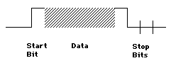
When at rest, when sending a logical 0 or when sending stop bits (at the end of each burst), the signal wire is at the negative voltage. When sending a logical 1 or a start bit (at the beginning of a data burst) the signal wire is at the positive voltage.
As for the data itself, the least significant bit (LSB) is always sent first.
The speed of an interface is given in bits per second (bit/s or bps), which is often confused with a modem’s baud rate. As a rough approximation, the bit rate divided by ten equals the byte rate in bytes per second (byte/s). For example, 9.6 kbit/s is roughly equivalent to 960 byte/s. Higher speeds are usually given in KB per second (KB/s) or MB per second (MB/s)
Common bit rates for RS-232 and RS-422 include:-
| bit/ | 50 | 75 | 110 | 134 | 150 | |
|---|---|---|---|---|---|---|
| kbit/ | 1.2 | 1.8 | 2.0 | 3.6 | 4.8 | 7.2 |
| kbit/ | 9.6 | 14.4 | 19.2 | 28.8 | 38.4 |
as well as the many other rates that are employed for modems.
In older equipment, 9.6 kbit/s is often used as a default speed. Fortunately, this slightly faster than the speed of older dot matrix printers that were originally connected to this kind of port.
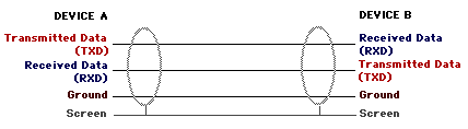
This interface is also known as CCITT V.24. Although data is sent along a single wire, with another for any data going in the opposite direction, there are also several control circuits.
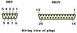
A computer is normally configured as data terminal equipment (DTE) and is commonly fitted with a 25-way D plug (DB25), although more modern machines come with a 9-way plug (DB9). Both types of connector are illustrated below.
A modem should be configured as data circuit-terminating or data communication equipment (DCE) and usually has a DB25 or DB9 socket. The connection between modem and computer therefore consists of a plug-to-socket cable with pin-for-pin connections.
A printer is usually configured as DTE, with a DB25 or DB9 plug, although some printers have a DB25 socket. In most instances, a computer and a printer, both of which are DTE devices, can be connected using a socket-to-socket cable with swapped-pin connections. This is often known as null-modem cable, since a modem isn’t involved in the circuit.
The pin connections for DTE fitted with a DB25 connector are as follows:-
| Pin | Code | Function | I/O |
|---|---|---|---|
| 1 | - | Screen | |
| 2 | TXD | Transmitted | Output |
| 3 | RXD | Received | Input |
| 4 | RTS | Request | Output |
| 5 | CTS | Clear | Input |
| 6 | DSR | Data | Input |
| 7 | Gnd | Signal | |
| 8 | DCD | Data | Input |
| 9 | - | +volts | |
| 10 | - | -volts | |
| 11 | - | Spare | |
| 12 | SDCD | Secondary | Input |
| 13 | SCTS | Secondary | Input |
| 14 | STXD | Secondary | Output |
| 15 | DCE | Transmitter | Output |
| 16 | SRXD | Secondary | Input |
| 17 | - | Receiver | Input |
| 18 | - | Spare | |
| 19 | SRTS | Secondary | Output |
| 20 | DTR | Data | Output |
| 21 | SQD | Signal | Input |
| 22 | RI | Ring | Input |
| 23 | - | Data | Input |
| 24 | DTE | Transmitter | Input |
| 25 | - | Spare |
The following wiring is used for DTE fitted with a DB9 connector:-
| Pin | Code | Function | I/O |
|---|---|---|---|
| 1 | - | Spare | |
| 2 | RXD | Received | Input |
| 3 | TXD | Transmitted | Output |
| 4 | DTR | Data | Output |
| 5 | Gnd | Signal | |
| 6 | - | Spare | |
| 7 | RTS | Request | Output |
| 8 | CTS | Clear | Input |
| 9 | - | Spare |
The DB25 and DB9 connections for DCE is identical to DTE, except that the roles of input and output pins are reversed. In other words, the circuits are the same but inputs become outputs and vice versa.
The serial port on an RS-423 device can be tested using a loop test plug. For DTE this can consist of a 25-way socket with links wired as follows:-
| Pin | Code | Pin | Code |
|---|---|---|---|
| 2 | TXD | 3 | RXD |
| 4 | RTS | 5 | CTS |
| 8 | DCD | 11 | SSD |
| 20 | DTR | 6 | DSR |
or as a 9-way socket linked as shown below:-
| Pin | Code | Pin | Code |
|---|---|---|---|
| 3 | TXD | 2 | RXD |
| 7 | RTS | 8 | CTS |
| 20 | DTR | 8 | CTS |
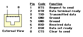
Some equipment uses an RJ45 connector for RS-232 ports, as shown below:-
A cable between DTE and DCE must be wired pin-for-pin, usually with a plug at both ends, although some devices require a socket. The cable screen (acting as an electrical shield around the other wires) and the signal ground (Gnd) circuits are usually connected at both ends.
A cable with conductors wired will always work but can be expensive. Varieties that only uses 5 or 8 wires are cheaper and are often satisfactory. The basic form of wiring consists of connections for TXD, RXD, RTS, CTS, DSR, DCD, DTR, as well as Gnd and shield wires. For a link that use software handshaking (see below) you only need three wires; TXD, RXD and Gnd.
This is slightly more complicated since you’ll need a cable in which the data circuits are swapped. Always remember that terms such as TXD and RXD refer to the function of the circuit as used in a conventional DTE to DCE link, not the roles of circuits as inputs and outputs. In other words you can have TXD inputs as well as outputs and RXD outputs as well as inputs!
For two DTEs the TXD output connection (pin 2 on a DB25) of one device must be joined to the RXD input (pin 3 on a DB25) of the second device, and similarly in the opposite direction.When connecting two DCEs each RXD output (pin 3) must be joined to each TXD input (pin 2).
Also known as CCITT V.10, this is similar to RS-232 but with the common wire connected to a differential input instead of ground. This prevents a data current following to ground, allowing the interface it to work at 1 Mbit/s over 1,000 metres of cable or at 100 kbit/s over 10 metres. The lower transition voltage of 4 to 6 volts is usually compatible with RS-232.
This balanced interface applies 5 volts alternately to one of two wires to indicate its logical state. It can operate at 10 Mbit/s over 10 metres of cable or at 100 kbit/s over 1,000 metres. This form of interface usually appears on a 9-way D connector (DB9) or 37-way D connector (DB37). The table below shows the connections for a 37-way D connector fitted to a printer:-
| Pin | Code | Function | I/O |
|---|---|---|---|
| 1 | Gnd | Signal | |
| 3 | SSD+ | Supervisory | Output |
| 21 | SSD- | Supervisory | Output |
| 4 | TXD+ | Send | Output |
| 22 | TXD- | Send | Output |
| 6 | RXD+ | Receive | Input |
| 24 | RXD- | Receive | Input |
| 7 | RTS+ | Request | Output |
| 25 | RTS- | Request | Output |
| 9 | CTS+ | Clear | Input |
| 27 | CTS- | Clear | Input |
| 11 | DM+ | Data | Input |
| 29 | DM- | Data | Input |
| 12 | TR+ | Terminal | Output |
| 30 | TR- | Terminal | Output |
| 19 | Gnd | Signal |
* Sometimes indicates printer cannot receive data (Ready/Busy protocol)
Pins 2, 5, 8, 10, 13 to 18, 20, 23, 26, 28, 31,32 to 37 not used
The port on an RS-422 device can be tested using a loop test plug, consisting of a 37-way plug with links wired as follows:-
| Pin | Code | Pin | Code |
|---|---|---|---|
| 4 | SD+ | 6 | RD+ |
| 22 | SD- | 24 | RD- |
| 7 | RS+ | 9 | CS+ |
| 25 | RS- | 27 | CS- |
| 13 | RR+ | 3 | SSD+ |
| 31 | RR- | 21 | SSD- |
| 12 | TR+ | 11 | DM+ |
| 30 | TR- | 29 | DM- |
Note that the original Macintosh computers had an RS-422 interface on a 9 way D connector (DB9) wired as follows:-
| Pin | Code | Function | I/O |
|---|---|---|---|
| 1 | Shield | Screen | |
| 2 | +5V | For | Output |
| 3 | Gnd | Signal | |
| 4 | TXD+ | Transmitted | Output |
| 5 | TXD- | Transmitted | Output |
| 6 | +12V | For | Output |
| 7 | CTS | Clear | Input |
| 8 | RXD+ | Received | Input |
| 9 | RXD- | Received | Input |
A standard RS-422 port doesn’t accept negative voltages and therefore can’t provide a reliable interconnection with RS-232 devices, unless the latter uses TTL voltages. However, although the ‘classic’ Mac port shown here conforms to the RS-422 standard, it also accommodates an RS-232 signal whenever the positive wire of an input pair is linked to ground.
This older type of interface is used for connecting a teleprinter or Telex machine. Logic 1 is represented by a flow of current, logic 0 is indicated by no current flowing.
Handshaking is a recognised protocol that allows two asynchronous devices to communicate their intention to send or ability to receive data. In other words, handshaking provides flow control for the transfer of data. Two systems are used: hardware handshaking and software handshaking.
Hardware handshaking uses extra handshake wires between the two devices. This is essential for the connection between a computer and a serial modem when working at 9.6 kbit/s or higher. Common hardware handshaking methods include RTS, CTS and DTR, as described below:-
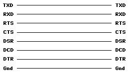
This provides the standard form of flow control for a DTE to DCE link. In this situation all the circuits in the interconnecting cable should be wired pin-for-pin, as shown below:-

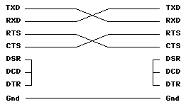
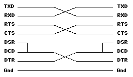
The cable that connects two DTEs is known as a null-modem cable since no modem is used. Several types of null-modem adaptor or cable are available. The one below employs RTS/CTS handshaking, implemented by exchanging the RTS (output) and CTS (input) lines. The DTR outputs are linked to the DSR and DCD inputs to disable DTR handshaking (see below).
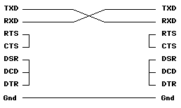
The null-modem cable shown below works with software handshaking (see below), so the RTS and CTS circuits are ‘linked out’ to defeat their operation. Once again the DTR outputs are linked to the DSR and DCD inputs to defeat DTR handshaking.
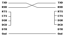
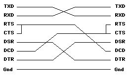
The next null-modem cable is again intended for software handshaking, in this instance with devices that lack DTR outputs. In this example the CTS outputs are used to set all three inputs:-
This kind of handshaking is used for flow control as an alternative to CTS handshaking. A high level on a DTR output indicates that DTE is ready to accept data. In a standard DTE to DCE link all the circuits in the interconnecting cable are wired pin-for-pin as shown below:-
The following null-modem cable, for joining DTE to DTE, provides both CTS/RTS and DTR handshaking. The DTR outputs feed both the DSR and DCD inputs of the other device:-
The next cable configuration can be used where RTS/CTS handshaking isn’t used, usually when software handshaking is in operation, but where DTR control is still necessary. The RTS outputs are ‘linked out’ to the CTS inputs of each device and to the other device’s DCD inputs:-
Software handshaking uses additional codes within the data to control the actual data flow. Since these instructions must be handled by software some timing delays are inevitable. Software handshaking may be used in conjunction with hardware handshaking (see above) or on its own.
Common software handshaking includes XON/XOFF and ENQ/ACK, as described below:-
This is the most common system. However, to make it work it may be necessary to ‘link out’ some hardware handshake lines. Usually this involves joining CTS to RTS, and, in some instances, to the DTR inputs. A null modem cable used for connecting two DTEs often has such links.
XOFF, represented by an ASCII control code called DC3 (hex 14, Control-S), tells the sender to suspend transmission, whilst XON, also known as DC1 (hex 11, Control-Q) lets it resume. Most printers send out an XOFF message when the printer’s interface buffer is nearly full.
This is an alternative system that’s rarely encountered. The two devices must be set up to work with the same block size and the transmitter then checks that the receiver is ready to accept data.
When the sender’s ready to transmit it puts out a control code called ENQ (hex 05, Control-E). If the receiver can accept a full data block it replies with ACK (hex 06, Control-F).
©Ray White 2004.
